Choosing the Right Straining Element
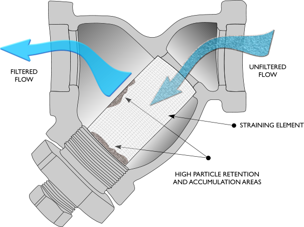
A strainer is installed into a pipeline and functions as a mechanical filter removing and retaining particles too large to pass through yet allowing the flowing media to pass unobstructed. By cleaning the flowing media, pipeline strainers help to protect expensive downstream equipment such as pumps, meters, spray nozzles, compressors, and turbines. Straining of the pipeline flow is accomplished via a perforated or mesh lined straining element, internal to the strainer. This is shown in the illustration below.
One of the more common questions asked when specifying a pipeline strainer is: “What perforation or mesh should be used for this application?” Before I go any further, I think it would be wise to discuss the terminology used when talking about pipeline strainers. Typically, the internal perforation or mesh material is referred to as a screen, when talking about “Y” strainers, and a basket, when talking about basket strainers. However, this can cause some confusion since the term “basket” can be used for both the strainer housing and the internal perforated or mesh material. To avoid this confusion, this article will use the term “straining element” when referring to the perforation or mesh material internal to the strainer housing.

Determining Opening Size:
The first decision that needs to be made is the hole size of the perforation or mesh. The general rule of thumb is the hole opening size should be one-half the diameter of the largest allowable particle. The largest allowable particle is defined as the size of particle that can pass through downstream equipment without causing damage. For example, if the maximum allowable particle is 1/16 inch than the perforation/mesh opening would be specified at 1/32 inch.

In addition to the size of particles, the quantity of debris in the flowing media must also be considered when determining the appropriate opening size.
Straining elements can only be used to remove insoluble floating impurities. The most common range of particle retention is 1 inch down to 40 microns (.0015 inch). The graph below shows sizes of common particles and compares them to perforation and mesh sizes.

A common mistake is to specify a hole opening that is to small for the application. This can lead to over-straining and should be avoided for the following reasons:
- Maintenance costs are significantly increased due to excessive cleaning requirements.
- Pressure drop is increased dramatically.
- The straining element may become damaged and fail.
In some applications requiring finer filtration, it may be advisable to strain in gradual steps. This is accomplished by placing progressively smaller straining elements in series.
Important:
Straining elements are not designed to withstand the same pressure as the strainer housing. If the straining element becomes fully clogged, it will be exposed to the same pressure as the housing. In most cases, this will cause the straining element to fail. A convenient way to monitor the differential pressure is to install pressure gauges on both the inlet and outlet sides of the strainer. It is not recommended to allow the differential pressure to exceed 20 psi.